Combined Droop Nose trailing edge airfoil
This project is performed on the airfoil's aerodynamic characteristics such as Lift, Drag, and Stalling angle. The Software used to accomplish the project are X-Foil, CATIA, and ANSYS Fluent flow. Basically, I have designed and simulated two different airfoils i.e. base-line airfoil(NACA 0012) and a morphed airfoil. To design an airfoil I performed a trial & error method using X-Foil as shown in Fig 1. from that code I developed X & Y coordinates which are used to create an airfoil in CATIA and performed a surfacing operation in CATIA and extracted the solid object to ANSYS to perform analysis. I have used ICEM software for meshing by spacing technique. Finally, Simulations are performed on both the airfoils and by the contours results, it's seen that the performance of the morphed airfoil is increased by 6.5% as compared with the baseline (NACA 0012) airfoil.
X-Foil
This code is used for extracting the airfoil design by the trial &error method.

airfoil design.
This picture shows the outcome design from the code mentioned above.

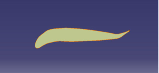
Morphed airfoil.
This pitcher shows the morphed airfoil using CATIA Software. Its seen that a 2D sketch is converted into solid body.
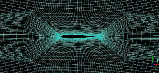
Meshing the base-line airfoil.
The normal airfoil is meshed using ICEM CFD software. I have calculated used the spacing technique between each node. Overall nodes were about 3 million nodes.
Meshing the morphed airfoil.
Similarly, I have meshed for morphed airfoil as well.

Pressure Countour plots.
This pitcher shows the pressure counters on the morphed airfoil for different angles of attack.

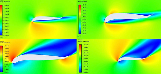
Velocity Contour plots.
This pitcher shows the velocity counter plots for the morphed airfoil for different angles of attack.